


User's manual
GLOSSARY
| Active window | A window (tab) in the program in which you configure or display the current graphic elements |
| The active state of the graphical interface of the program | A state where when you hover the mouse over this item the color changes |
| Heuristic algorithm (heuristics) | The algorithm for solving the problem, including a practical method that is not guaranteed to be exact or optimal, but sufficient to solve the problem. Allows you to speed up the solution of the problem in cases where the exact solution can not be found |
| Metaheuristics | A high-level strategy for finding an approximate solution, based on some simple concept applicable to a wide range of tasks, based on one or more lower level heuristics |
| Genetic algorithm | Heuristic search algorithm used to solve optimization and modeling problems by random selection, combination and variation of the desired parameters using mechanisms similar to natural selection in nature |
| Mutations | Mutations are similar to reproduction, from mutants choose a certain number of test solutions (individuals) and change them in accordance with pre-defined operations |
| Population | All generations contributing to the next. In the parts placement algorithm, a random set of random solutions |
1. APPOINTMENT
The program «C-MES: Cutting for Laser and CNC» is designed to optimize the cutting of rectangular and arbitrary parts from metal, wood-based panels, stone, cardboard, etc. C-MES: Cutting for Laser and CNC can be used to cut sheet materials laser on laser and waterjet cutting machines, on CNC milling centers and for manual material cutting. C-MES: Cutting for Laser and CNC is an easy-to-use, modern program with a well-designed, simple and convenient user interface. Calculation of cutting can be performed for rectangular parts and blanks, as well as for parts and blanks with an arbitrary configuration. Despite its simplicity, with C-MES: Cutting for Laser and CNC you can achieve significant waste reduction.
2. PROGRAM INSTALLATION
To install the program, unpack the file «C-MES_Cutting Setup 2.1.4.zip» downloaded from https://c-mes.co.uk/products/c-mescutting-for-laser-and-cnc/. Double-click it and launch the installation wizard. Follow the installation wizard instructions. After installation, a shortcut will appear on your desktop named «C-MES_Cutting»
3. LAUNCH OF THE PROGRAM
Double-click on the shortcut to launch C-MES: Cutting for Laser and CNC, the following window should appear:

4. SETTINGS
When you click the second bookmark in the upper left «setting» with the icon ![]() the program settings window will open:
the program settings window will open:

Section «Nesting configuration»
| Display units | Choice of units (inches / mm) | |
| Space between parts | The minimum distance (mm) between the placed parts. If you plan to use the merge function of common lines, this value is set to zero |  |
| Curve tolerance | When calculating the placement, curved sections should be turned into segments. Curve tolerance is the maximum allowable error when performing this approximation. A higher value is set to speed up the placement process, and a lower value when greater accuracy is required |  |
| Part rotations | The number of turns that you need to try when placing parts. For example, if 8 turns are used, some parts will have a 45 degree angle. Four turns are usually enough, making it easy to combine common lines for rectangular parts. Higher turns can help if you have geometrically complex parts |  |
| Optimization type | Optimization type - three types implemented: |  |
| 1.Gravity | minimizes placement width. This is well suited when used to place a rectangular sheet, and you must use leftovers for cutting other parts | |
| 2.Bounding Box | reduction of common rectangular borders. This mode is best for material preservation when only a small part of the sheet is used | |
| 3.Squeeze | reducing the total area, while you can place parts that are not rectangular. It is best to use it for sheets of complex geometric shape, or when all sheets are filled and there is no space left in them | |
| Use rough approximation | Using approximations. Certain geometries can be very time consuming to calculate, for example, several hundred unique snowflakes. To speed up the calculation process, it is recommended to use a simple polygon approximation, and the material consumption may increase. If your vector is not unique (i.e. several hundred identical snowflakes), using the «quantity» field is another way to significantly speed up the process |  |
| CPU cores | The number of parallel nested processes. 2 - for most laptops; 4 - for most desktops |
Section «Import/Export»
| SVG scale | Scale to import from SVG. Sets the conversion factor between inches / mm to SVG units (pixels - px). Typically, files produced using Adobe Illustrator's vector graphics editor are set to 72 units / inch, and for files with Inkscape, 90 units / inch. The scaling factor can be obtained from the SVG file itself, but when it is not available, these values are used |
 |
| Endpoint tolerance | Tolerance (inch, mm) of convergence of the end points of closed loops. Real vectors are often inaccurate, sometimes the points from one path to another do not exactly match to form a closed path. Try increasing this value if you have problems importing the file |  |
| DXF import units | The choice of units of measurement (pixel, inch, mm) when importing data from a DXF file | |
| DXF export units | Choice of measurement units (pixel, inch, mm) when exporting data to a DXF file |
Section «Laser options»
| Merge common lines | The option to merge common lines. If set, the edges of the parts that are in contact will be merged into one line when exported. Combining common lines ensures that the laser passes through each line only once, reducing the time of cutting and thermal deformation. The option is also useful when calculating cuttings for circular saws to reduce the number of longitudinal and transverse cuts |  |
| Optimization ratio | Coefficient optimization. When placing parts, it is necessary to determine which is more important - saving time or material. When the optimization coefficient is 0, the placement is calculated only on the basis of material savings. When this ratio is 1, saving time is considered as important as saving material |  |
Section «Meta-heuristic fine tuning»
| GA population | Genetic algorithms are a form of machine learning that mimics biological evolution. A smaller population size may produce results faster, but will have less genetic diversity. A larger population size can give better results by increasing processing time |  |
| GA mutation rate | The coefficient that determines the number of mutations in the population in each subsequent test. A higher mutation rate ensures that a wide variety of placement options will be tested, but the ability of the algorithm to use previous successful placement options is reduced. Increase this value if there are obvious mechanisms that he does not seem to investigate |  |
When you hover the mouse cursor over the active parameter area, a brief explanation of the current settings item may be displayed in the left margin of the settings window.

5. CUTTING
After starting the program, the main form (item 3 of the user's manual) opens, on which the button is active «Import»:

When you click this button, the «Opening» dialog box opens in which you need to select a file with the details that need to be placed (the figure shows example.svg file).

After pressing a button «Opening» on the form of the program on the right - on the “example.svg” tab there will appear the figures contained in the selected file:

The left side of the program window displays a table with 5 columns:
1. «Label» - the part label that is displayed later when displaying the cutting variant, and which the user can change (can accept characters and numbers) by clicking on the value:

2. Simplified Detail Column
3. «Size» - dimensions of the part (mm or inches - depending on the selected settings - p.4 user's manual)
4. «Sheet» - a column with a checkbox for selecting the part (s) on which (which) other parts will be placed. The choice is made by clicking the mouse on the square opposite the selected part. After selection, the «Start nest» - button becomes active - the start of placement of parts (marked with a green circle in the figure).

The correct choice in this case is determined by only one criterion - the placed part must have overall dimensions not exceeding the part on which it is supposed to be placed. In case of an incorrect choice, the program will try to calculate, but it will not produce the result.
5. Speaker «Quantity» - the number of placed parts (only numbers), which the user can also change by clicking on the value:

The user can sort all the figures for each of the columns having the name: «Label», «Size», «Sheet», «Quantity» by clicking on the name.
It is possible to delete a part or several parts; to do this, select the parts to be deleted by clicking the mouse on this part (when you click on the «Select all», button shown in blue in the figure, all parts are selected):

After a part is highlighted, the button marked with a red circle in the figure becomes active. When you click on it or on the «Delete» button on the PC keyboard, the selected parts are deleted and further deleted parts are not used in the calculations.
The program also provides for the addition of rectangular parts with specified dimensions. To do this, press the button marked in the figure with a green circle. After clicking on this button, the interface to add the «Add Rectangle» rectangle shapes appears in the lower left part of the program window:
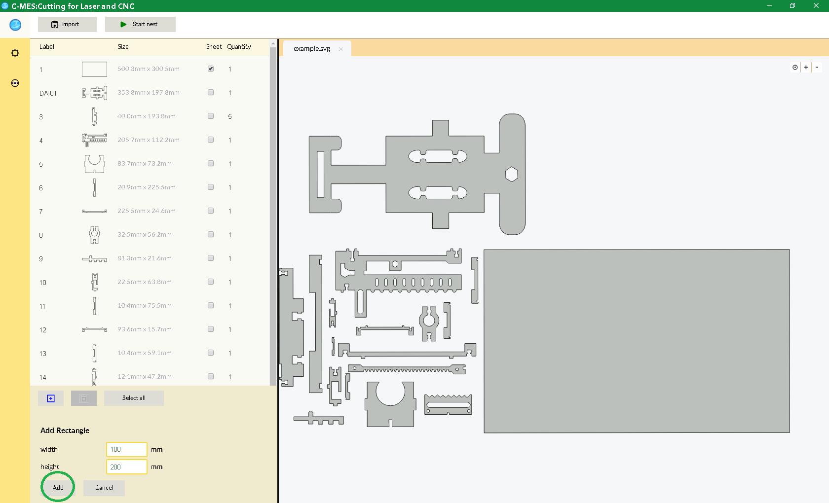
In the «width» window, the width of the rectangular part (sheet) is set, in the «height» window, the height of the rectangular part (sheet) is set. After setting these parameters, the «Add», button is pressed, marked with a green circle in the figure - the added figure appears at the end of the parts list. When you click the «Cancel» button, the interface for adding shapes closes.
After the required number of parts has been selected for placement and the sheet on which the selected parts are supposed to be placed, we press the «Start nest» - after which an empty program window initially opens, where the process of placing parts with active buttons is displayed in green:
«Stop nest» – stop calculating accommodation
«FixPl» – fixing the current placement
«Back» – return to the initial window of the program
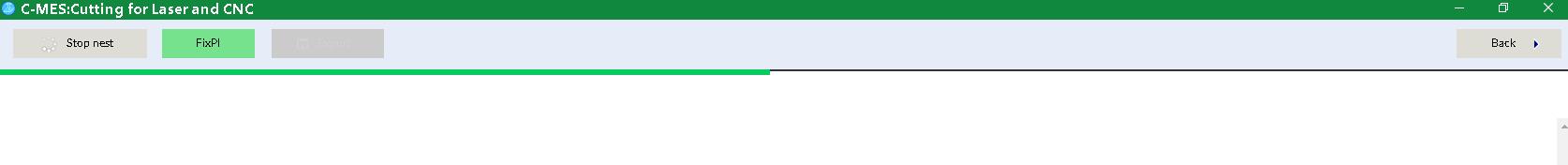
At the end of the process, when the placement progress indicator reaches the extreme right part of the program window, the «Export» . button becomes active in this program window. The field on the right will display the first option for placing parts with white names on a gray background, corresponding to the names (tags) in the «Label» column. The algorithm implemented in the program is based on training, i.e. to calculate the subsequent options for the use of previous options. Thus, placement optimization is performed.
The first accommodation:

Subsequent accommodations:

On the left, on the screen, the buttons display the current placement parameters:
 |
The number of sheets (sheets) on which parts are placed |
 |
Number of parts placed / total number of parts to be placed |
 |
The total area of the placed parts (how many percent does this area occupy on the sheet (sheet) where they are placed) |
 |
Each lane is its own placement.
KMU’ – the ratio of the minimum area of the rectangle in which all the figures are placed to the area of the sheet. KMU’’ – the ratio of the sum of the areas of all placed figures to the minimum area of the rectangle in which all the figures are placed. |
When you click on any placement bar, the corresponding placement option is displayed on the right and the number of placed parts in this option in the «parts placed» field. To export the desired placement option, click the «Export» button - a drop-down list appears in which you select the file format you want and enter the name of the exported file, then click the «Save» button:

The exported file can always be opened later in this program and see the selected placement option or run the calculation again:

In this case, the location of the parts recorded in the file does not affect the results of the subsequent calculation.
With the «FixPl» button - the current placement is fixed, after pressing this button you can see which parts and how many of them remain unplaced. To do this, press the «Back» button and then the initial screen opens with a list of unplaced parts:

Those parts that are all placed - their number will be zero, as can be seen from the figure - are not placed, there are 15 and 16 details left. After that, we can place only the remaining parts or add new ones and start the placement process with the added figures on the next sheet.
6. REQUIREMENTS TO THE STRUCTURE OF IMPORTED FILES.
6.1. General requirements
In order to avoid any problems in further interpretation of imported cutting elements in CAM systems (Autodesk ArtCAM, SolidCAM, etc.), the following rules should be observed:
- unsuitable elements (points, regions, OLE-objects, 3D polylines, forms, etc.) are deleted from the drawing;
- the drawing is made flat;
- double and superimposed lines are not allowed;
- convert splines and ellipses to polylines;
- all objects are transferred to one layer;
- all types of lines are solid;
- all primitives must be zero line thickness;
- all contours must be closed;
- avoid (if possible) sharp corners, round all sharp corners with a small radius arc, in this case, the cutting head of the machine will not have to stop to change the direction of motion, and as a result you will get the same cut quality throughout the entire trajectory. The arc radius must be at least the width of the cut, which for laser cutting machines is 0.2 ... 0.3 mm, but not too large so as not to disturb the functional and geometrical characteristics of the part;
6.2. SVG files
The program supports syntax according to the SVG specification version 1.1. For the program to work correctly (correct import of cutting elements), it is necessary that the contours of the parts be represented as non-fragmented SVG elements and are closed or closed.
A figure with several closed contours must be necessarily represented in the file using the SVG path element. In addition, each individual detail (the figure of any complexity) must be contained in its path, i.e. The number of path must be equal to the number of figures.
When using the SVG path element, you must observe the following rules:
- the M command must be unique for the current closed loop (this ensures the continuity of the loop and the correct application of the fill attributes, colors, etc. to this loop);
- if a complex figure is transmitted through the SVG format (for example, the internal cutout-hole in the part), each closed loop must be completed with the Z command.
- m should not be present.
When preparing vector images of parts in such well-known graphic vector editors as Inkscape, Adobe Illustrator, etc. for subsequent cutting - SVG files are formed in accordance with the above requirements.
6.3. DXF files
To correctly import cutting elements from DXF files, elements of graphic primitives and graphic primitives should be placed in the BLOCKS section. If there are several contours in one part, all the contours of this part must be presented in one BLOCK section. This is necessary for the effective use of exported cutting elements in preparation for production in CAM-programs.
